Advantages and optimization of crossed helical gears with steel worm and plastic wheel

Source: L. Becker, Chair IFA, Ruhr-University Bochum

Introduction

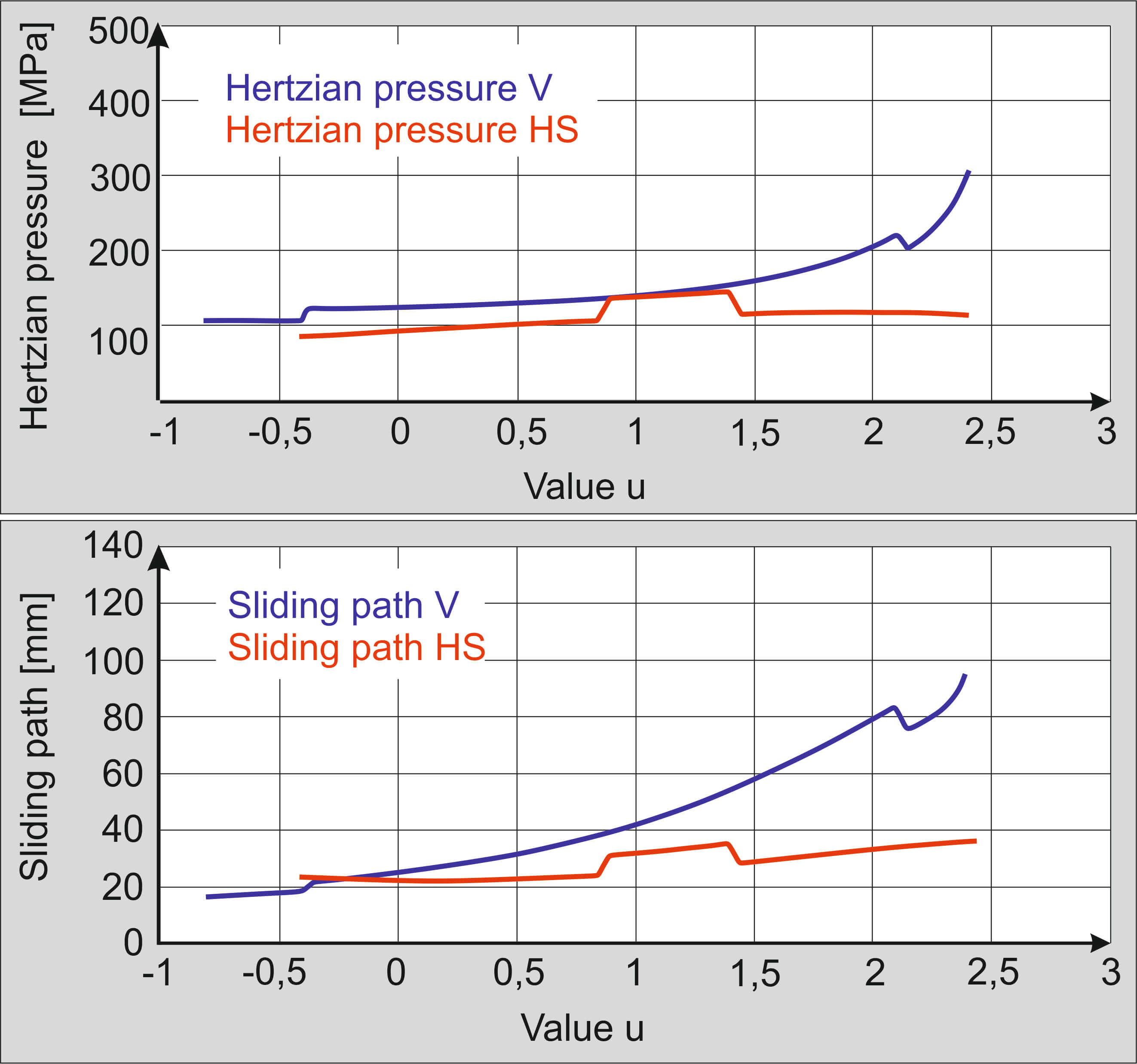
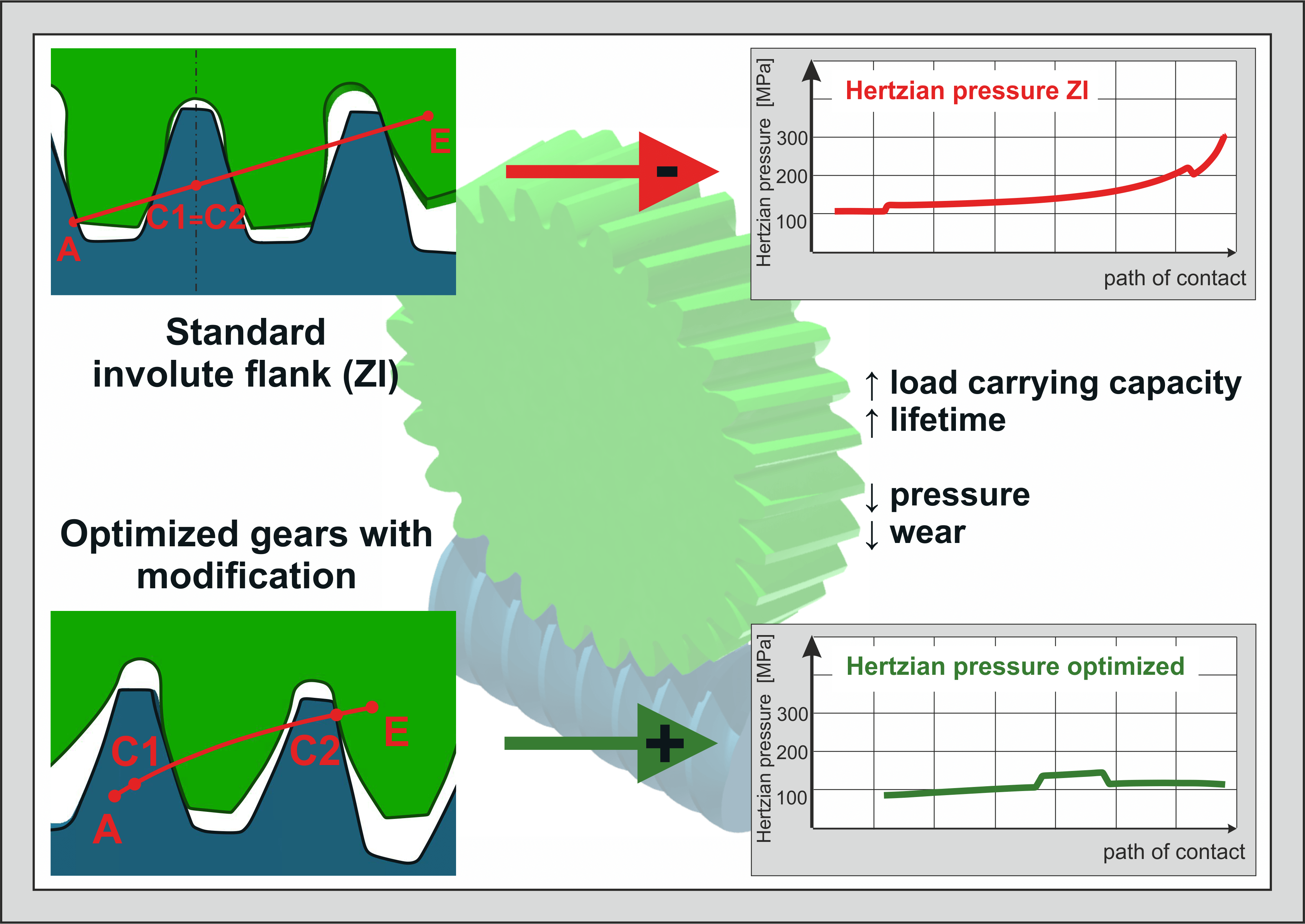
Crossed helical gears paired with steel-worm and plastic-wheel are a commonly used but comparatively under-studied form of gearboxes. Primarily they take part in actuators, power take-offs and position units as well as in the process automation. As high-performance plastics are developed, plastic gears can increasingly replace steel applications. Crossed helical gears with a plastic wheel are lighter, less expensive, and advantageous in terms of vibration and noise damping. Current research shows optimization possibilities for pressures, sliding paths and thus the load capacity and lifetime. The transfer of flank geometries from other types of gears to crossed helical gears leads to a pressure optimization up to 30%.

State of Research

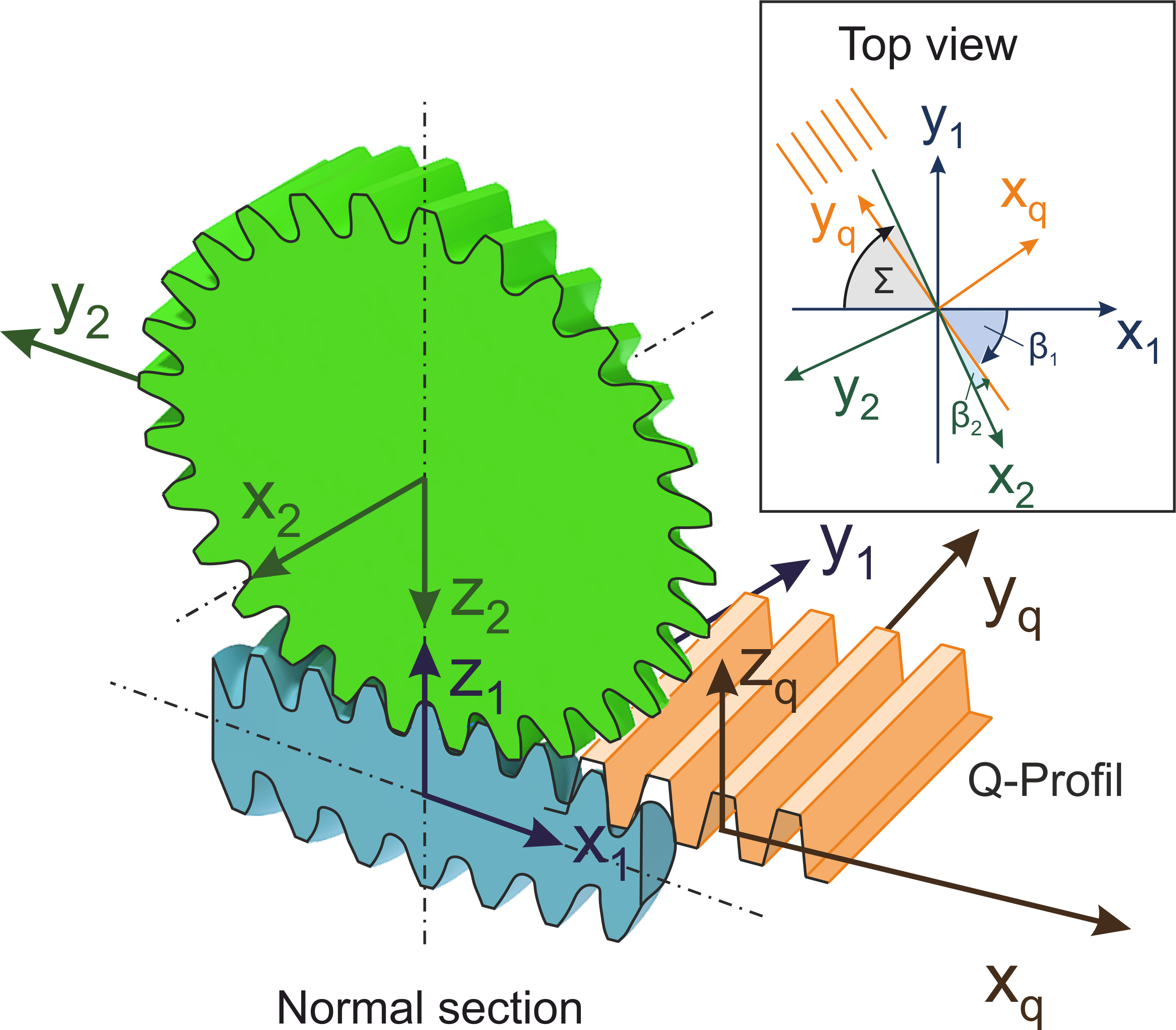
Fundamentals and calculations of crossed helical gears based on the work of Niemann and Winter [1]. They derived the geometry in the transverse section with a thin counterpart rack arranged in space. Two steel gears were considered, for which the calculation of pressures, efficiencies and sliding paths are conducted after the geometry derivation. According to Niemann and Winter, a screw point is a prerequisite for the running ability of a crossed helical gear. The parameters are calculated in the so-called screw point.

Today, industry is mostly using crossed helical gears with steel worm and plastic wheel. The behavior of plastic in gears has been studied in scientific work. VDI Guideline 2736 summarizes important contents and provides an overview of the influences of the plastic material to be considered.

The applications of crossed helical gears require high efficiency in a small space. Compared to other types of gearboxes, there is no maintenance strategy that provides a wheel or lubricant change at a specified time interval. To fit the requirements in the best conceivable way, it is necessary to understand these gears in detail.

New calculation for general and optimized crossed helical gears

Current research at the Chair of Industrial and Automotive Drivetrains are focusing on the geometric adaptation of the flank contour. Regarding other gear types, the involute is not the best possible optimization in every case. In worm gearboxes, the ZC geometry has become established. In particular, the good smoothness behavior of the concave-convex pairing proves lower surface pressure. In helical gears, an S-profile modification often occurs. The change in curvature of the flank shape still occurs in the active working flank and not at the transition to the tooth root fillet curve. This prevents high pressure at the end of meshing in the tooth root area. The advantages of these flank shapes were transferred to crossed helical gears in a new calculation software and provide verifiable optimizations.

Figure 1: Coordinate systems of the worm, wheel and counterpart rack for the profile generation

The advantage of the new calculation algorithm is that all types of flank shapes and profile modifications can be calculated. This was not possible with the previous programs and limits the choice for finding an optimized gear. As with Niemann and Winter [1], the geometries of both gears are derived from the profile of a counterpart rack. The latest research is considered, which extend the range of valid crossed helical gears. It is proven that the screw point is not a necessary criterion. There are many gears without this point that run optimally [2]. Furthermore, crossed helical gears are insensitive with respect to deviations of the axis crossing angle and when choosing the helix angles. These can be freely selected and do not have to add up to the axis crossing angle. Often, the knowledge about the tolerances of worm gearboxes is "daunting" for users due to the similarity of the gears. The tolerances for crossed helical gears are much wider. During installation, it is not necessary to check the contact pattern. Consequently, they are much easier to manage.

The calculated transverse geometries can be processed in two ways. On the one hand, they are transformed into 3D models and prepared for additive manufacturing. In this case, the optimized gears can be tested and evaluated directly on a test rig without deviations. On the other hand, the meshing behavior will be analyzed. A parameter network describes the flank surface in vector form. Principal curvatures and principal curvature directions can be calculated using general formulas for any type of curved surface. With this information and knowledge of size and position of the contact ellipses, flank pressures and sliding paths can be calculated.

Results and positive effects of the flank optimization

By transferring the ZC and S geometry, the high pressures at the start and end of meshing were reduced. The declining characteristic curve of the S-profile modification at the end of contact leads to a reduction in flank pressures up to 60%. The ZC geometry optimizes the areas around the pitch point of the gearing/the pitch points of the gears in the transverse sections (no screw point). The concave-convex contact results in a reduction of pressure up to 29%. The flank pressure in the contact point is proportional to the third root of the tooth normal force. Reducing this value by 30% allows twice as large tooth normal forces and torques. Similar effects can also be seen when considering the sliding paths. The sliding paths on plastic gears are significantly higher and more critical than on steel worms. Depending on the flank modification, this can be reduced by up to 50% at critical points. This is an enormous advantage regarding flank wear and lifetime of crossed helical gears.

Figure 2: Optimized crossed helical gear with a combination of the ZC and S geometry; pressure and sliding path on the plastic wheel along the entire contact path; Reference gear V compared to the optimization HS

The wide range of applications is an advantage about the variety of parts. The production of worms is usually expensive and complex. The geometry of the worm depends on the manufacturing tool. Different wheel geometries can be produced for a fixed worm geometry. In this way, one worm can be used to serve different gear applications with individual requirements.

More details on this topic will be presented at the International Conference on High Performance Plastic Gears.

Authors

Linda Becker, M.Sc.,
Research Assistant at the Chair of Industrial and Automotive Drivetrains, Ruhr-University Bochum

Prof. Dr.-Ing. Peter Tenberge,
head of the Chair of Industrial and Automotive Drivetrains, Ruhr-University Bochum

References

[1] Niemann G., Winter H.: Maschinenelemente Band 3, Springer-Verlag 1960

[2] Boehme C.: Berechnungsverfahren zur Erweiterung der Anwendungsgrenzen und der Optimierung von Schraubradgetrieben, Ruhr-Universität Bochum, 2020